
Please watch the video above, it gives you a overview of what my slider looks like, how it operates and what it can produce. Enjoy!
This project started when I found the video on the right hand side, it is an advertisement video for a Rhino motion EVO slider. After being amazed by the capabilities of this camera accessory, I proceeded to look at the price of it.
To my surprise I found out the accessory was over $500. This seemed a little much for something that carries a camera along a short distance.
And so, this project was born.


After doing much research I proceeded to create the electronics of the camera slider. Without a ‘clean’ movement produced by the motor the camera would shake too much during the time-lapses and therefore ruin the shot. Therefore I had to find a motor capable of moving very slowly and precisely. After much consideration I chose to use a standard stepper motor like the type you would find in a 3D printer. Also, an arduino nano, stepper motor driver, LCD and a few other components would also be needed.
Once I was happy with my schematic I proceeded to construct my circuit on a breadboard. As you can see from the pictures the breadboard was a bit of a mess but it worked! I was able to control the speed of the stepper motor and the movement was very smooth.
The next step was for me to move the circuit to a more permanent set up on a Perf/Vero board.


Unfortunately, my original idea of using a Perf/Vero board didn’t go to plan. The setup was just to delicate, there were too many jumper wires and it just wasn’t suitable for the job. Therefore, I proceeded to design and make a PCB for my circuit.
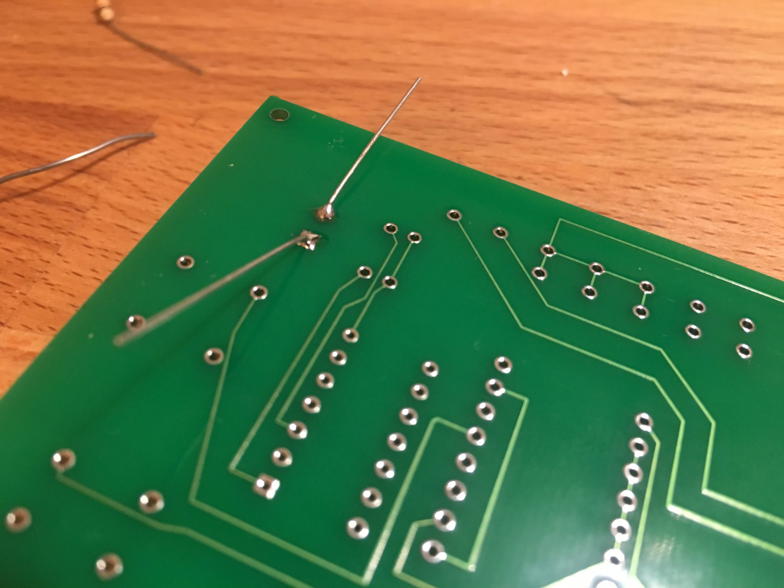
This was my first time making a PCB so I stuck with just a 2 layer board but with the help of the free online software Easyeda I was able to create one quite easily. I then got 5 PCBs manufactured to my specification from China (only cost me $9.99).
As you can see from the images the PCBs looked great.
Finally, I moved all the components over to the PCB and tested everything once again and as expected it was still working. Having the circuit on a PCB also made mounting it much easier as I had small holes drilled in the corners of the PCB to help with mounting.


Now that all the electronics were out the way I could get on with designing the actual slider.
Everything was going to be built around a V-Slot 20x80mm rail, this is a very common way of making anything that requires a carriage to move (like CNC machines etc…). I then went on to design different parts of the design such as the legs, electronics mount, carriage and much more (see images). Everything was going to be made using a 3D printer except for the carriage itself which would be sheet aluminium.
I used the CAD software, Solidworks to allow me to draw all of my parts in 3D and get these amazing renders you can see on the left hand side. I then tested everything by inserting all the seperate parts into a large assembly and once I was happy I proceeded to print all the parts


3D printing is a great way of making high quality parts with precision relatively quickly. Many of the pieces I designed had very small tolerances in order to work but the printer was able to manage them perfectly.
Some of my parts were made using PLA while others were made using ABS, it depended on if the part was going to be visible and how strong it need to be.
There were many miss prints for some of the larger parts just just to the complexity but eventually I had all my parts printed. However, due to how many of my parts were made there was a lot of support material needing removed on almost all of my parts. Some of the material was so well stuck, it took me many hours to remove it all.


Now that all the parts were completed, I was able to start assembling the full slider.
Once ready, i plugged in a batery and began to test.
Here are various pictures and videos of the slider while I was testing it.
All in all, the project was an overwhelming success an gained 100% in my A2 Design and Technology coursework